Intro
Elektrosluch was created by Jonáš Gruska from LOM record label, based in Bratislava, Slovakia.
Loose translation of Elektrosluch in English is “electrohear”. It’s a device that allows us to listen to electromagnetic fields.
Jonáš did a write up for Makezine’s Weekend Project serie. That inspired me to build one myself.
Build
Plans for Elektrosluch DIY version are released under GPL v3. You can find them at LOM’s Github account.
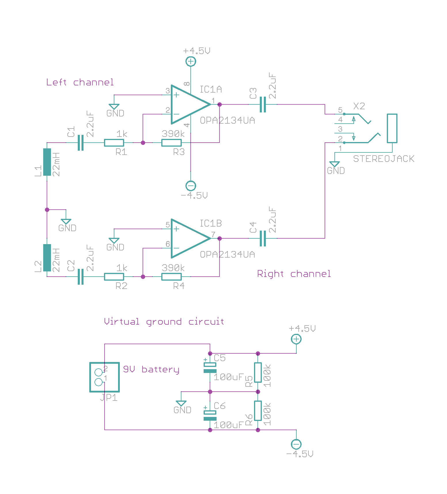
Elektrosluch schematic (GPLv3), above, borrowed from https://github.com/LOM-instruments/Elektrosluch-DIY
I ordered the OPA2134PA-ND and 22mH inductors from DigiKey. The rest I bought from a local components supplier.
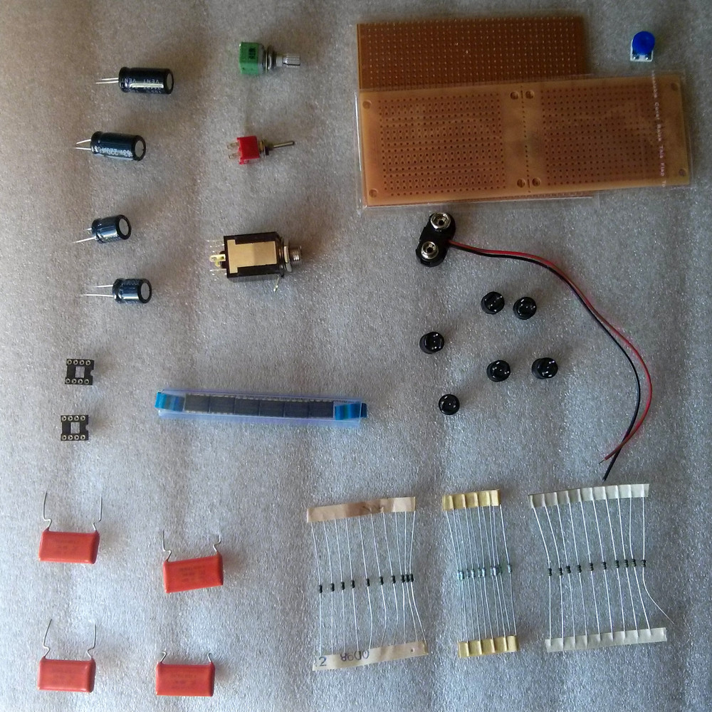
Above, all parts for Elektrosluch DIY and some more for later improvements, or future versions.
I couldn’t find 2.2uF matalised polyester capacitors, so I ended up buying 1.5uF, which should filter out more bass frequencies picked up from 50Hz (eg. main power) lines than 2.2uF.
Once I had all required components I got onto it and after an hour-ish of work, I had the first version of my Elektrosluch working.
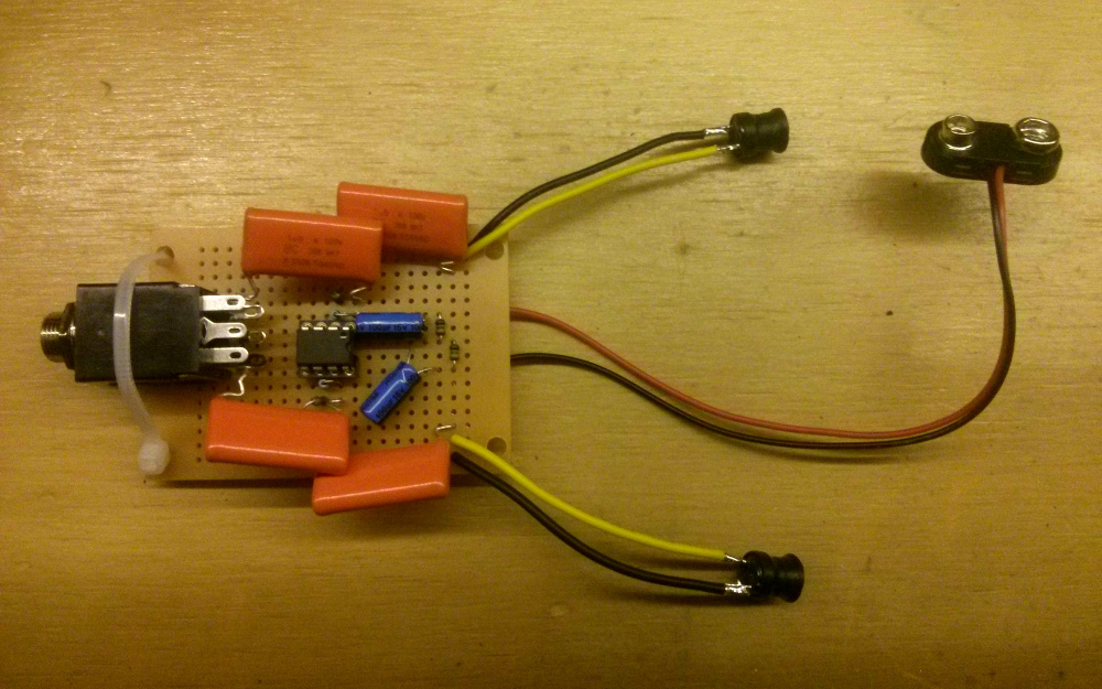
Above, done v1 on an ultra mini experimenters board.
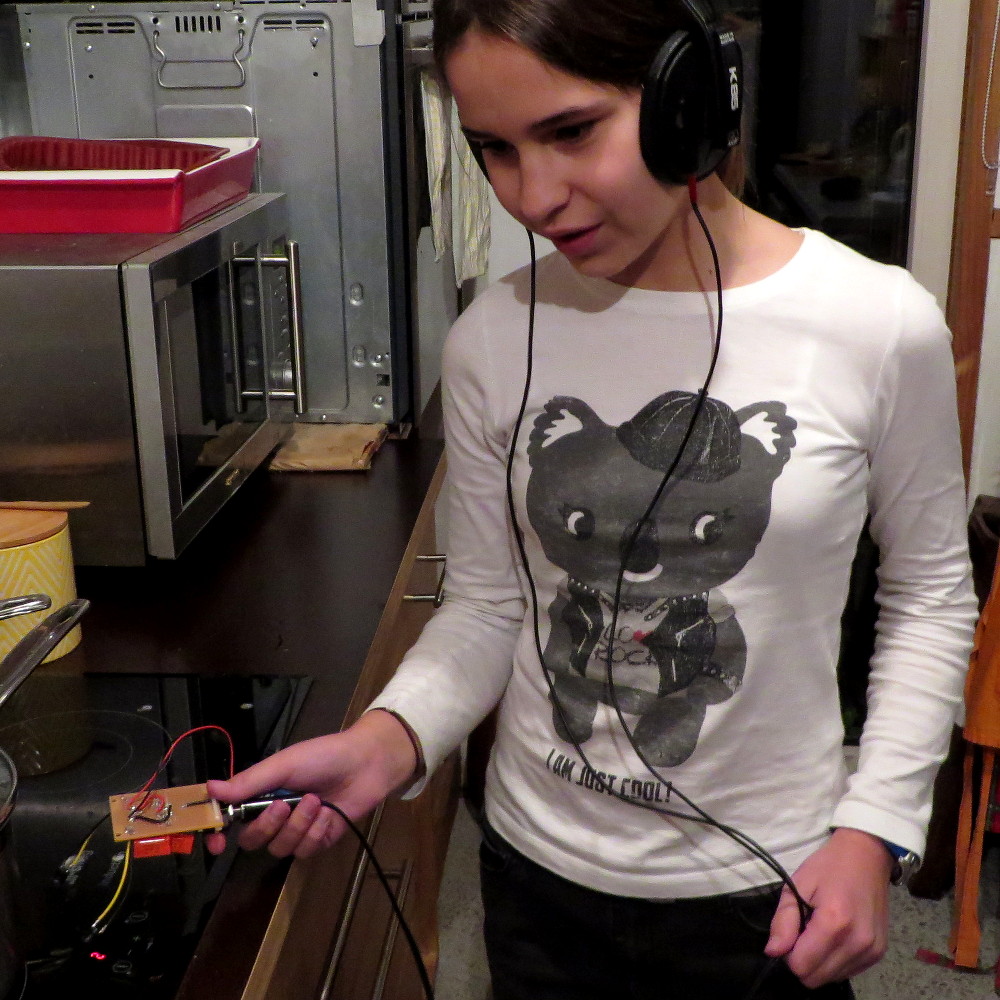
Above, Elektrosluch DIY, in action.
This is a nice little DIY project. Definitive sign of success was that both of my kids used it around the house and loved the discovery of objects that do and don’t produce electromagnetic fields.
Parts
Elektrosluch DIY
Elektrosluch:
- 1pc - Stereo jack
- 1pc - prototyping PCB
- 4pcs - 1.5uF (Metalised Polyester Capacitor)
- 2pcs - 1kOhm Resistor
- 2pcs - 390kOhm Resistor
- 2pcs - 22mH Inductor
- 1pc - OPA2134PA-ND Integrated circuit
Virtual ground:
- 1pc - 9V battery snap
- 2pcs - 100uF (Electrolytic Capacitor)
- 2pcs - 100k Resistor
Comments
comments powered by Disqus